Construction of Alternator (Synchronous Generator)
An alternator, also called a synchronous generator, is an AC machine that converts mechanical energy into electrical energy. Unlike DC machines, the alternator has its armature winding on the stator (stationary part) and the field winding on the rotor (rotating part). This unique arrangement simplifies insulation design for high-voltage output and eliminates the need for commutators.
Alternators are the primary source of electrical power in power stations worldwide — from hydroelectric dams to thermal and nuclear plants. Understanding their construction is essential for any electrical engineer.
Stator Construction
The stator is the stationary outer frame of the alternator. It houses the armature winding from which the electrical output is taken. The main components of the stator are:
- Stator Frame: Made of cast iron for small machines or welded steel plates for large machines. It provides mechanical support and protection.
- Stator Core: Built from thin laminations of high-grade silicon steel (0.35–0.5 mm thick) to minimize eddy current losses. Laminations are insulated with varnish and assembled together.
- Stator Slots: Cut on the inner periphery of the core to hold the three-phase armature winding.
- Armature Winding: A three-phase distributed winding placed in stator slots. It can be lap-wound or wave-wound depending on voltage and current requirements.

Stator of an Alternator showing laminated core and slots
Rotor Construction
The rotor carries the field winding and is supplied with DC excitation through slip rings and brushes. The rotor produces the main magnetic flux that cuts the stator conductors to generate EMF. There are two types of rotor construction:
- Salient Pole Type — used in low and medium speed machines (hydro turbines)
- Cylindrical Rotor Type — used in high-speed machines (steam and gas turbines)
Salient Pole Rotor
The word "salient" means projecting. In this construction, poles project outward from the rotor core surface. Key characteristics:
- Large diameter and short axial length
- Non-uniform air gap — minimum under pole centres, maximum between poles
- Pole faces shaped to produce sinusoidal flux distribution
- Concentrated field windings wound around each pole
- Operates at low speeds (120–500 RPM)
- Typically has 4 to 60 poles
- Vertical shaft mounting (common in hydroelectric plants)
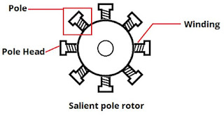
Salient Pole Rotor — poles project outward from the core
The rotor core is made of steel laminations to reduce eddy current losses. Damper windings (short-circuited copper bars embedded in pole faces) are provided to damp rotor oscillations during transient conditions and to help start synchronous motors.
Cylindrical Rotor (Non-Salient Pole)
Also called a smooth or non-salient pole rotor. The rotor is machined from a single solid steel forging to form a smooth cylinder with no projecting poles.
- Small diameter and long axial length
- Uniform air gap throughout
- Distributed field winding placed in slots cut on rotor surface
- Operates at high speeds (1500–3000 RPM)
- Usually has 2 or 4 poles
- Horizontal shaft mounting
- Lower windage losses due to smooth surface
- Mechanically stronger — withstands high centrifugal forces
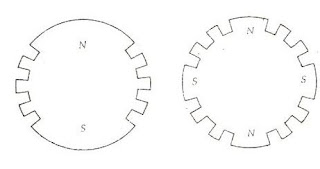
Cylindrical Rotor — smooth surface with distributed winding in slots
Salient Pole vs Cylindrical Rotor — Comparison
Excitation System
The field winding on the rotor requires DC supply to produce the magnetic flux. This DC supply is called excitation. Common excitation methods include:
- DC Exciter: A small DC generator mounted on the same shaft provides field current through slip rings.
- Static Excitation: AC output from the alternator itself is rectified using thyristors and fed to the field winding via slip rings.
- Brushless Excitation: An AC exciter with rotating armature and stationary field. Output is rectified by rotating diodes mounted on the shaft — no slip rings or brushes needed.
Cooling Methods
Large alternators generate significant heat due to copper and iron losses. Cooling methods include:
- Air Cooling (OA): For small machines up to 50 MVA
- Hydrogen Cooling: Hydrogen gas (7× better thermal conductivity than air) for machines above 50 MVA. Reduces windage losses by 90%.
- Water Cooling: Direct water cooling of stator conductors for very large machines (500 MVA+)
EMF Equation of Alternator
The RMS value of EMF generated per phase in an alternator is given by:
Where:
- f = frequency (Hz) = P × N / 120
- Φ = flux per pole (Wb)
- Tph = number of turns per phase
- Kw = winding factor = Kd × Kp (distribution factor × pitch factor)
For a 4-pole alternator at 50 Hz: Ns = 120 × 50 / 4 = 1500 RPM
Applications of Alternators
- Thermal, hydro, nuclear, and wind power plants
- Diesel generator sets for backup power
- Marine and aviation power systems
- Automobile alternators (claw-pole type) for battery charging
- Portable generators for construction and emergency use
Frequently Asked Questions
1. Why is the armature winding placed on the stator in an alternator?
Placing the armature on the stator eliminates the need for slip rings to carry high-voltage, high-current output. It simplifies insulation design and allows easier cooling of the high-power winding.
2. What is the difference between salient pole and cylindrical rotor?
Salient pole rotors have projecting poles, large diameter, short length, and run at low speeds (hydro plants). Cylindrical rotors are smooth, have small diameter, long length, and run at high speeds (thermal plants).
3. Why are damper windings provided on salient pole rotors?
Damper windings (short-circuited copper bars in pole faces) suppress rotor oscillations during sudden load changes and help in starting synchronous motors by providing induction motor action.
4. What is the typical speed of a cylindrical rotor alternator?
Cylindrical rotor alternators typically run at 1500 RPM (4-pole, 50 Hz) or 3000 RPM (2-pole, 50 Hz). In 60 Hz systems, speeds are 1800 RPM and 3600 RPM respectively.
5. Why is hydrogen used for cooling large alternators?
Hydrogen has 7 times better thermal conductivity and 14 times lower density than air. This reduces windage losses by about 90% and provides superior heat removal, enabling higher power ratings in compact designs.